When testing various jewelry, we need to choose the right XRF spectrometers. Just like the detector (the “heart” of the device) and the algorithm (the “soul”), the optical path plays an essential role in determining how well the device performs. You can take the optical path as the “blood vessels” that ensure every part works smoothly.
Two spectrometers may have the same detector and algorithm but perform very differently due to their optical paths. For example, the XF-A5 and XF-A5S differ in optical paths and A5S does better at detecting complex samples. With the upgraded optical path, XF-A5S/S5/S6/S8 will be a good choice for jewelry factories who want more accurate analyses.
Let's take a look at two cases that show how the optical path impact test results.
Case A: composition analyses of a ring
As shown in the picture, the outer ring is silvery and the inner is golden. The black dot marks the spot to be tested.
Put the ring on a jewelry holder and make the dot above the center point of the testing film.

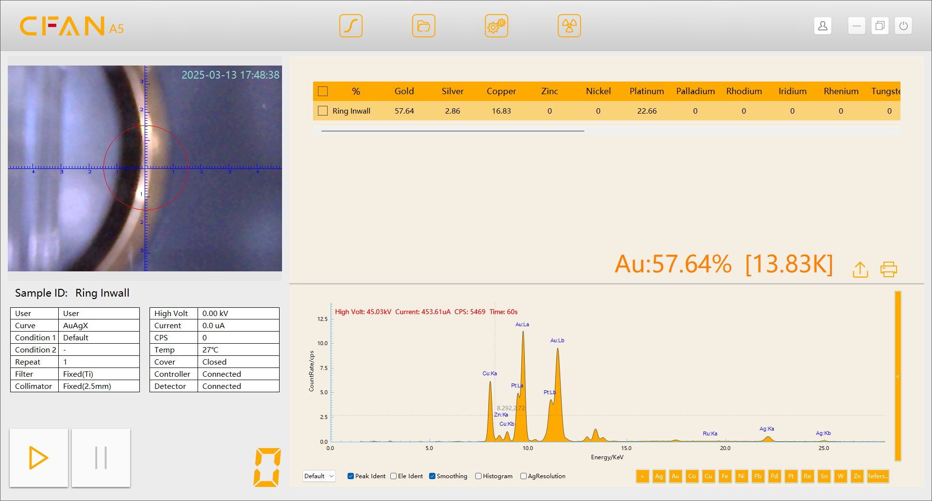
XF-A5 (collimator: Φ2.5mm): Because the camera focus is on the film, the image becomes blurry, when the target is not tightly attached to the film.
XF-A5SMC (collimator: Φ2.0mm): The X-ray and camera have the same focus and the focal distance can be adjusted for a sharper image.
XF-A5 (collimator: Φ2.5mm)
XF-A5SMC (collimator: Φ2.0mm)
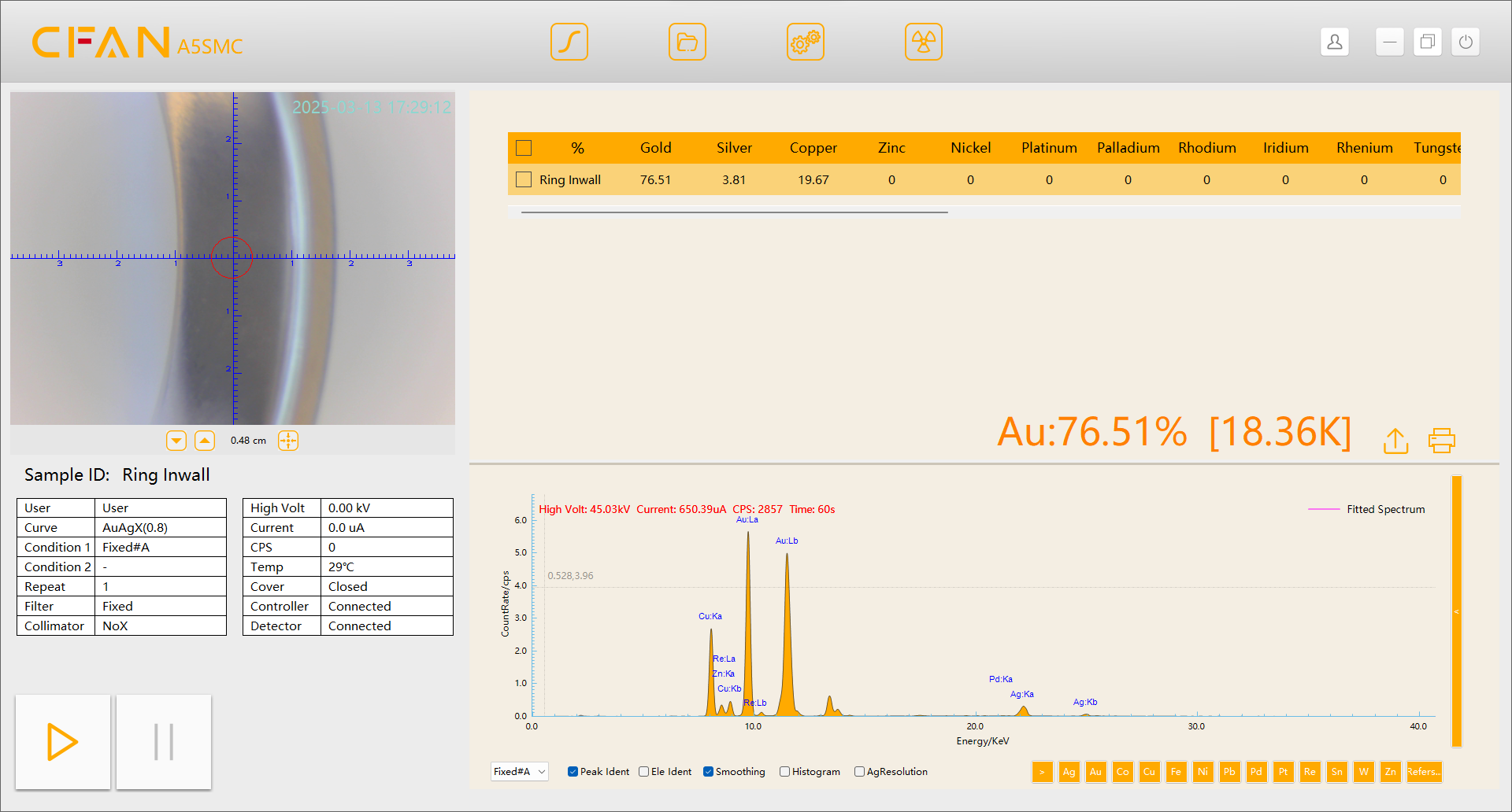
Test results: The slivery outer ring is made of platinum and the outer is made of K-gold. For curved samples, the XF-A5SMC's real focus is within the circle but XF-A5's one is beyond. Therefore, XF-A5SMC has a more accurate analysis.
Case B: testing a piece of inlay jewelry
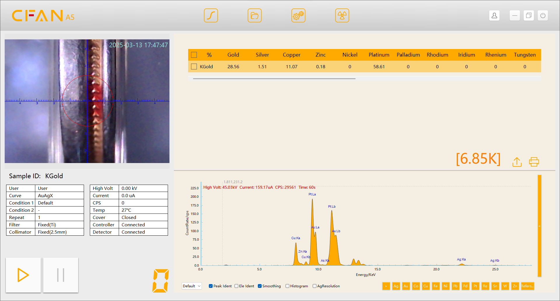
XF-A5 (collimator: Φ2.5mm): With a larger real focus, X-rays cannot be focused on the inlaid pattern, which lead to an inaccurate results.
XF-A5SMC (collimator: Φ0.8mm): With dual collimators and the 2nd generation 90° angle optical path, X-rays can be focused on the inlaid pattern, which bring an accurate results.
XF-A5 (collimator: Φ2.5mm)
XF-A5SMC (collimator: Φ0.8mm)
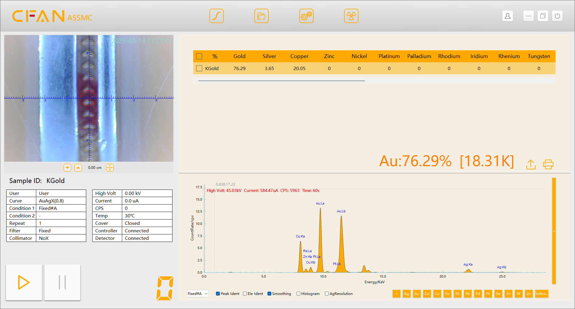
Test results: XRF spectrometers that comply with ISO23345 do well in detecting concave, inlay and small jewelry. For example, XF-A5SMC with dual collimators can provide reliable information. High-end products, such as XF-S5MC/S6/S8, are ideal choices for jewelry factories who want more precise data because they adopt multi-collimators and 90° angle optical paths.
The following will delve into the optical path that has such a significant impact on testing. What is it? How many types are there? What is the difference? What are the pros and cons?
Various optical paths can be divided into two types based on the incident direction of X-ray beams: upward and downward. The latter is going to be discussed.
The optical path involves the X-ray optical path and the sample image optical path.
The X-ray optical path
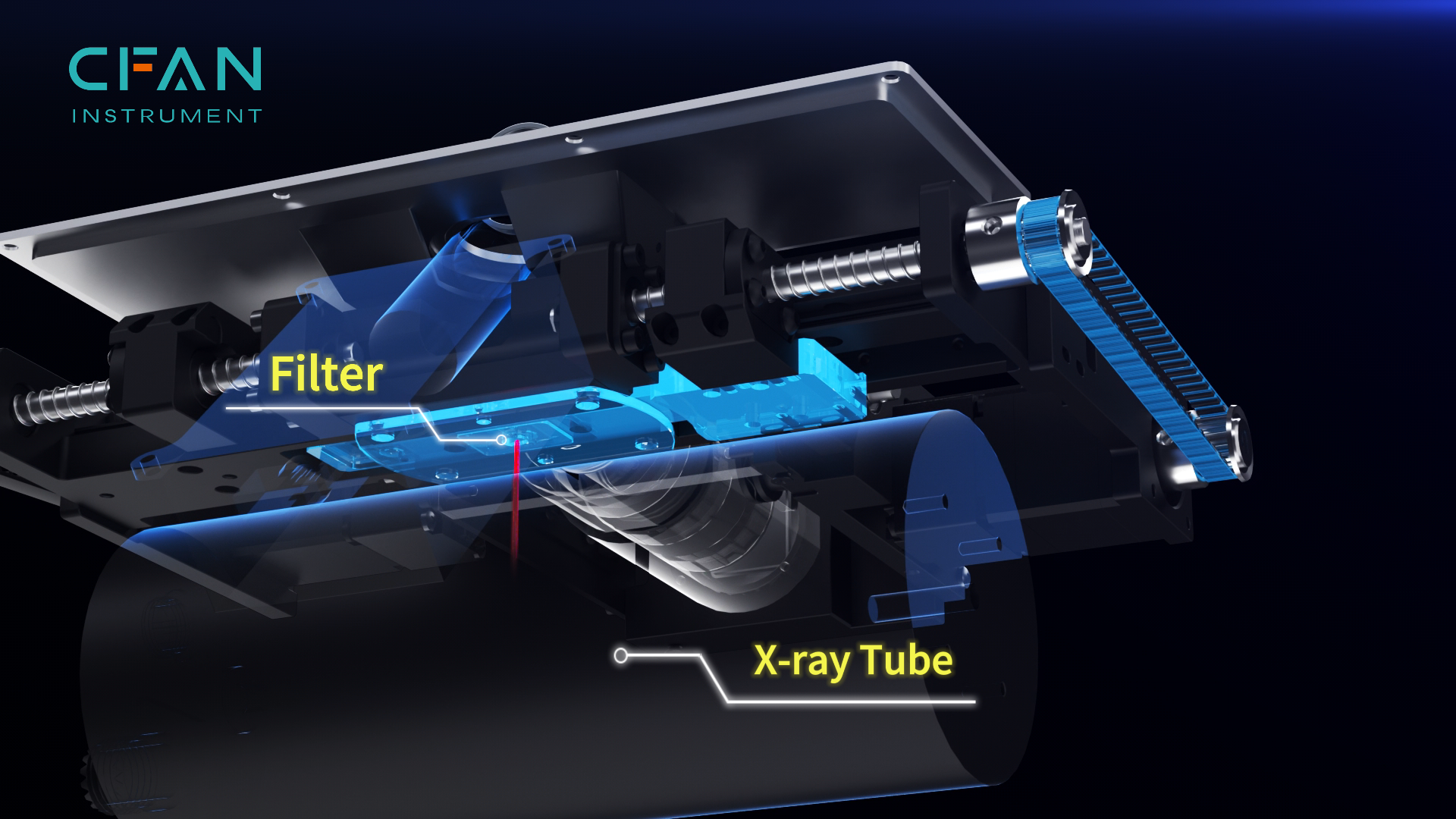
Application in XF-A5SMC
The X-ray optical path: the X-ray passes through the primary filter and collimator, interacts with the sample and excites the characteristic X-ray which are absorbed by the detector (shown as above). There is a more complex and uncommon structure that includes the secondary filter and collimator.
The sample image optical path
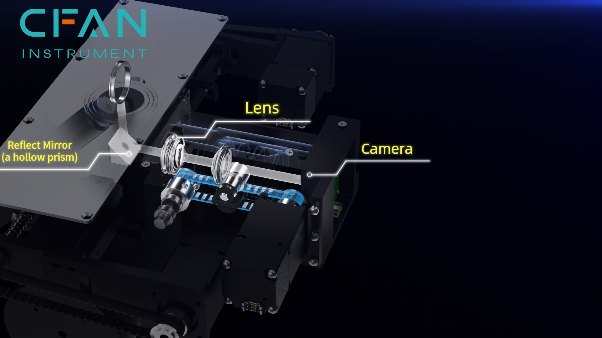
Application in XF-A5SMC
The sample image optical path: the visible light from the sample is captured by the camera.
Types of optical paths in energy dispersive X-ray (EDX) spectrometers:
1. Incident X-rays at an angle of 45°
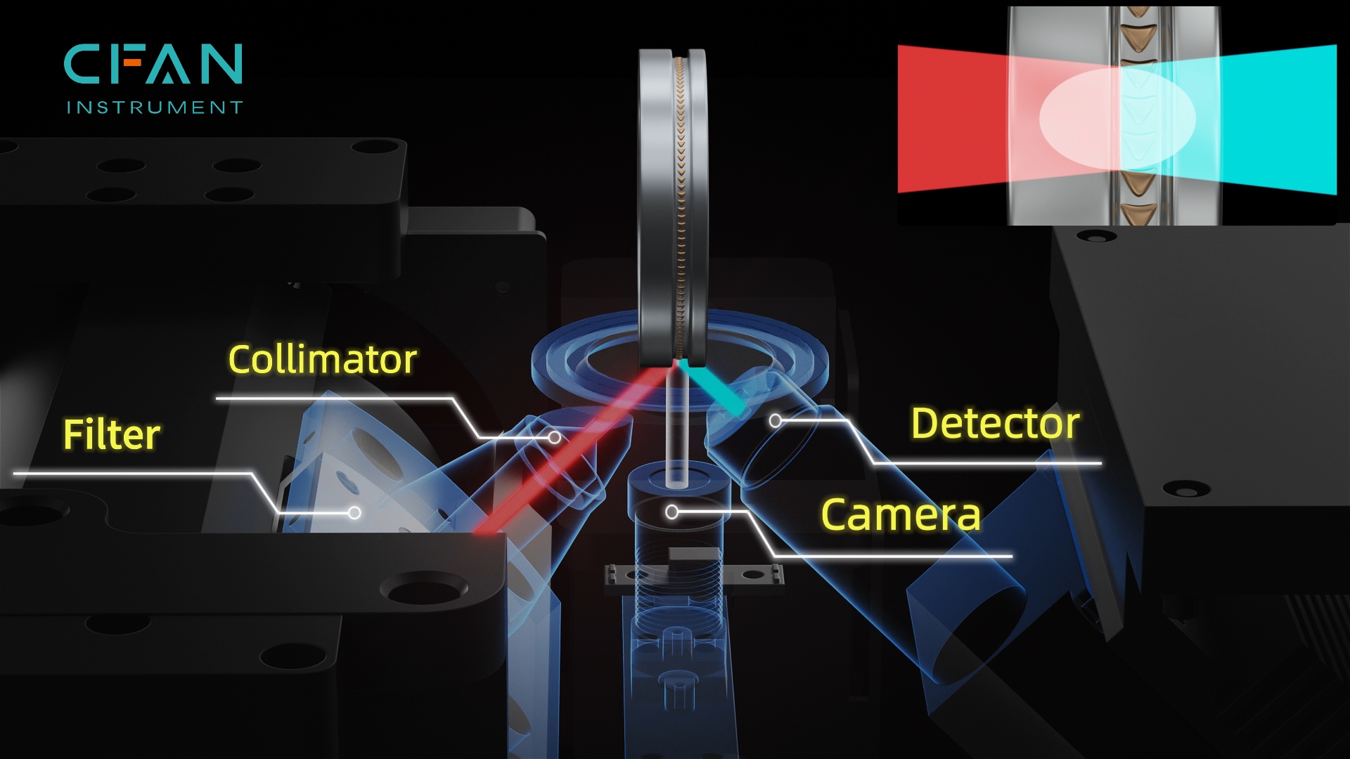
Figure 1-1 (application in XF-A5)
In Figure 1-1, generated by the tube, X-rays at a 45° angle pass through a filter and a collimator, interact with a sample and excite characteristic X-rays which are absorbed by a detector. A camera is below the sample to capture the image. The green pattern represents the area where X-rays meet the sample surface. The real focus is elliptical because the angle of incidence is 45°.

Figure 1-2
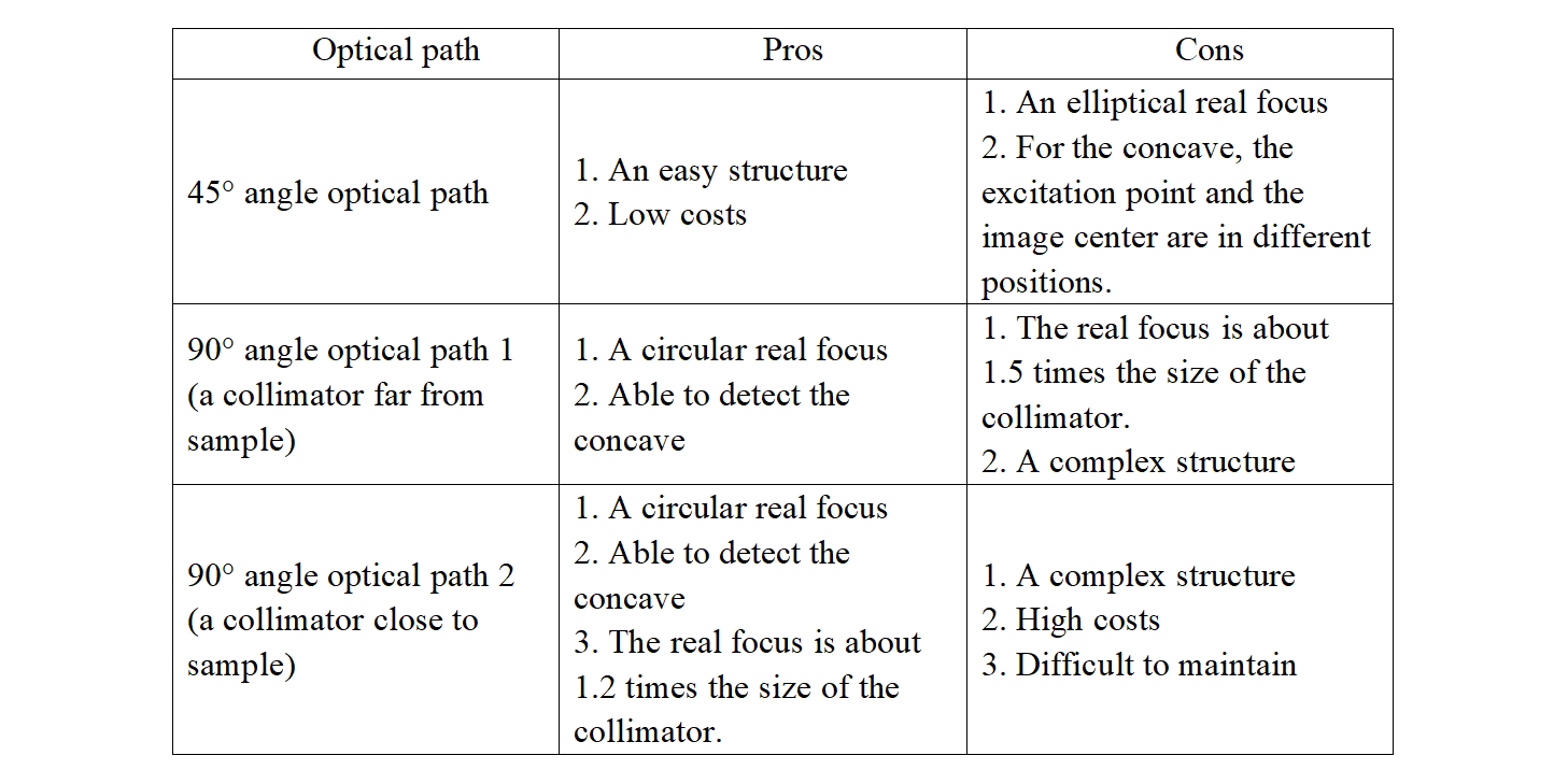
With a simple structure and low costs, the 45° angle optical path is adpplied to entry-level spectrometers. However, there are two drawbacks. First, the real focus is elliptical. Second, when the sample surface is concave, the excitation point and the image center are in different positions, as shown in Figure 1-2.
Note: The red represents the primary X-ray from the tube and the blue represents the characteristic X-ray from the sample. The excitation point, like the center of a sphere, emits characteristic X-rays in all directions.

For uneven or tiny samples, this optical path results in lower accuracy; for coatings, poor accuracy; for coatings in complex structures, terrible accuracy.
Most low-end spectrometers are equipped with the 45° angle optical path. So do A5 and K5 of CFAN Instrument.
2. Incident X-rays at an angle of 90°
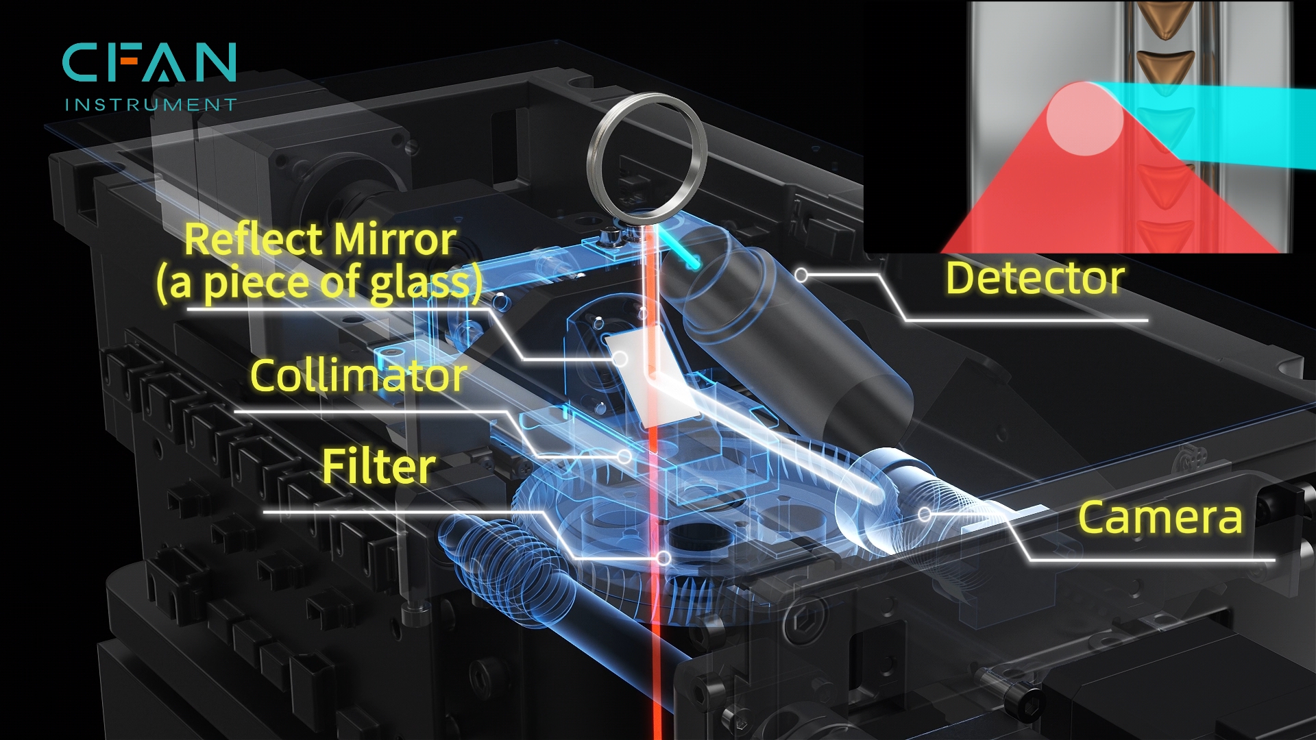
Figure 2-1 (application in the 1st generation XF-A5S)
In Figure 2-1, generated by the tube, X-rays at a 90° angle pass through a filter, collimator and mirror, interact with a sample and excite characteristic X-rays which are absorbed by a detector. A camera is parallel to the reflect mirror which refracts visible light from the sample. The real focus is circular because the angle of incidence is 90°.
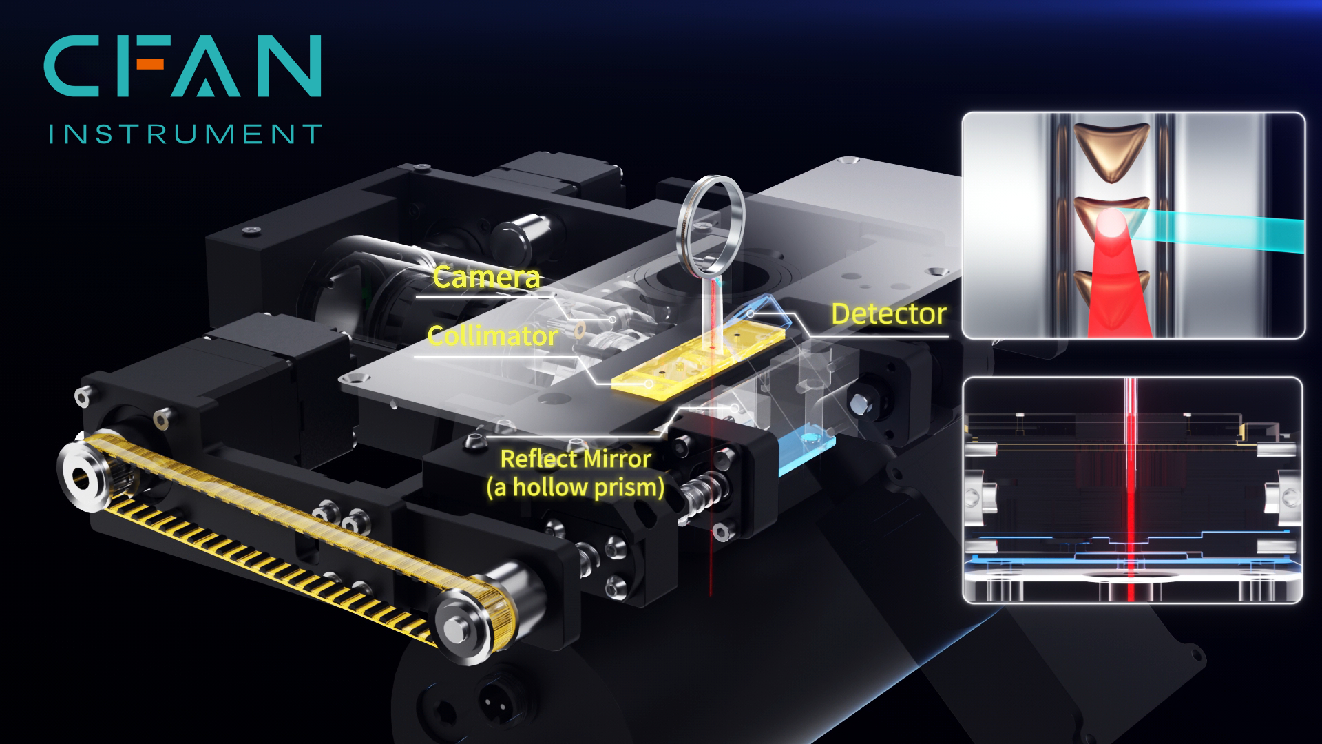
Figure 2-2 (application in XF-A5SMC)
In Figure 2-2, a collimator is on a reflect mirror and closer to a sample, which brings a smaller real focus. The mirror is a hollow prism for a cleaner image.
The two structures above can be called “the optical path with the same focus for X-rays and visible light” because the actual image central point overlaps with the X-ray excitation point.
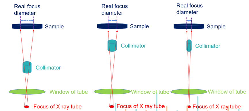
The two 90° angle optical paths are shown as below:

Figure 2-3
In Figure 2-3, collimators are 2.0mm in diameter but their real focuses are 3.0mm and 2.4mm in diameter respectively. The reason is shown in Figure 2-4. The farther the collimator is from the sample, the larger the real focus; the smaller the collimator aperture, the smaller the real focus when the collimator in the same position; the smaller the focus of the X-ray tube, the smaller the real focus.
The 90° angle optical path has significant advantages:
A. Its real focus is circular.
B. With the concave sample surface, the excitation point and the image center are in the same position.
C. Coating thicknesses of small samples (e.g. inlay jewelry or thin chains) can be measured by XRF spectrometers with the 90° angle optical path.
The optical path in Figure 2-1 is applied to few spectrometers such as CFAN’s XF-A5S/S5/S6 as well as certain products of Hita***.

The optical path in Figure 2-2 is common among the EDX spectrometer, including the 2024 series, P series and A7 of CFAN Instrument.

Similar optical paths are applied by Sp***, Fisc***, Hita***, Shima*** and so on. Besides, Ber*** makes full use of a camera motor to avoid complicated design. In summary, the 90° angle optical path is widely used in mid to high end products to minimize the real focus.
Below is a comparison table for the three optical paths:
The design of the optical path is complex since it takes into account factors such as filters, tube currents, counts per second (CPS), mutual interference, data stability, secondary excitation, and resolution.
In the long term, the 45° angle optical path will still be applied to low-end products, while the 90° angle optical path in mid and high end products will be optimized to achieve the smaller real focus.


